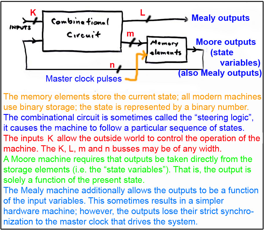
The storage elements discussed on the previous page-the flip flops and latches-are the basis of the finite state machine. The basic FSM topology is shown below:
Courses in logic design traditionally have always contained a section on the implementation at the gate level of the steering logic to produce desired FSM sequences. We will look briefly at that here. Many of these ideas also relate to programming since programs themselves are really FSMs; there is a logical structure, sometimes rather hidden in higher-level environments, that allows your program to remember where it is. In lower-level programs, one might set "flags" or use other similar methods. For example, you might set a flag to 1, then later in your code you may have something like "If (flag) then {whatever} else {something else}". In this case, flag is really a state variable.
Basic FSM terminology is shown below. I have created an arbitrary FSM state diagram here. In this example, we have four states needed. I will show the "binary encoded FSM" method here. Each state requires sufficient information to be stored to allow the machine to remember what state it is in. The binary number represents the minimum in terms of memory unit cost; in this case, two flip flops can store the state information for 4 states.
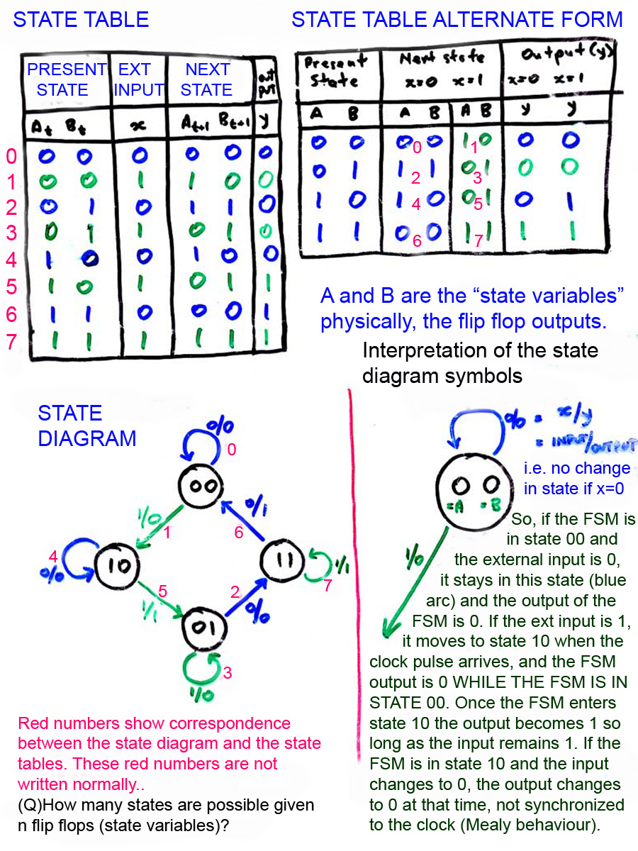
A point that often causes confusion is in the interpretation of the output variable. The Mealy machine is shown here. Remember that its output is a function of the input and the PRESENT STATE, that is, at the tail of the arrow, NOT the NEXT STATE.
The state diagram itself arises from some problem in the real world. It represents a type of specification of the problem, just like the flow or UML specifications you are SUPPOSED to use to plan your software! Now, given a particular state diagram, how is it actually converted to the hardware realization?
This is actually quite simple. I will use the D flip flops discussed on the previous page. [Other types of flip flops exist. For implementing FSMs, the JK flip flop is particularly favored. The behaviour of the JK is this: there are two inputs J and K, and two outputs Q and Q' as usual. To set Q to 1, J must be 1, K is don't care. To reset Q to 0, K must be 1, J is don't care. If both are 1, Q changes state, and if J=K=0, no change occurs (the storage state). Surprisingly, in spite of the fact that you must drive two inputs per bit, compared to a single bit for the D flip flop, the total gate count for the steering logic is almost always less, and is never more than for D. In the days of MSI circuits, the JK was a standard part and thus often used; a D implementation almost always needed more steering logic, i.e. more SSI-MSI chips. However, in these days of VLSI where we basically work at the transistor level, the transistor cost of FSM implementation using JKs or Ds is basically the same. JKs give a lower module cost in terms of MSI, but we are not using MSI packaging now.]
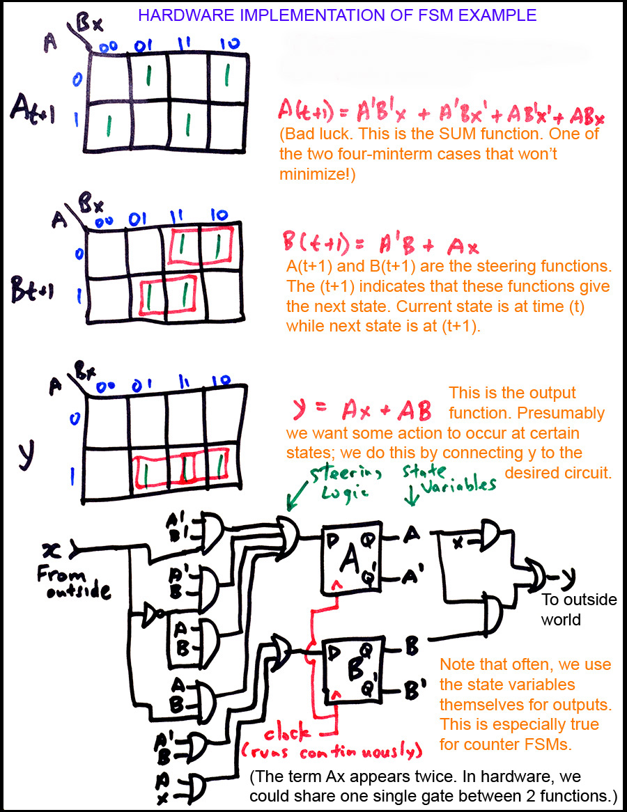
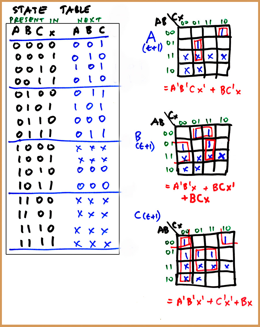
The design technique is sometimes called synthesis of a binary encoded FSM using excitation table method. Since a D flip flop's output (excitation) is simply a copy of its input at the clock pulse time, the steering or excitation functions are simply a tabulation of the next state value for each flip flop. So, looking at the first version state table in the diagram above, we see that flip flop A requires that its inputs prior to the clock must be the function
A(t+1)= F(A,B,x) = Sum(0,1,3,7) and
B(t+1) = Sum(2,3,5,7) while
y = Sum(5,6,7).
These functions can be implemented using the K map methods decribed on previous pages. The process and final circuit are shown below:
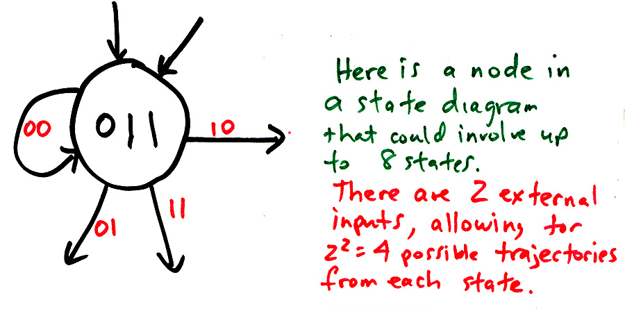
The diagram below shows one node for a FSM with two input variables:
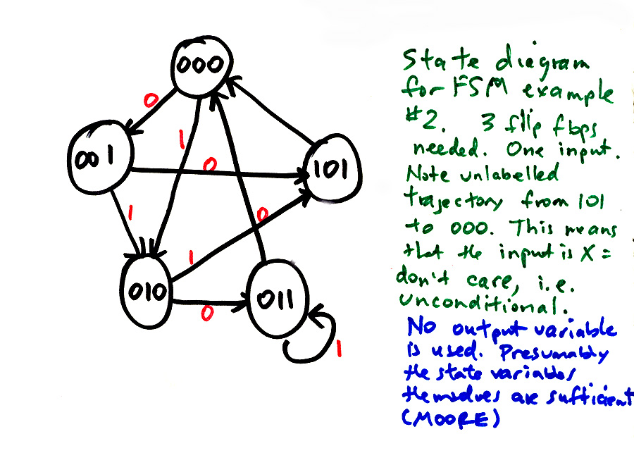
Another worked example of FSM implementation is below:
It is important to realize that the states are essentially concepts. The binary numbers are often of no importance in themselves; they could be anything so long as they are distinct for all the states. So, the states may conceptually be things like "Car has arrived from N side of intersection" or "A loonie has been deposited in the slot". Hardware implementation requires the binary state assignment.
This brings us to the state assignment problem. How do we decide which states are implemented using which particular binary numbers? Why do we care? Well, maybe a particular assignment will give the least amount of steering logic. There is no algorithm that will allow us to find the minimum case, except basic brute force. That is, design all the possible state machines, and see which one uses the fewest gates in its steering logic. As the number of states increases, the number of possible machines goes up as a modified factorial function, which means that, by about 10 states, we are getting into big trouble if we want to do this. Of course, with transistors so cheap, saving a dozen or two at a cost of considerable effort seems a bit silly.
(Q)Explain the state assignment problem.
We note that the second example just above there are only 5 states, represented by 3 bit values. So, we have three unused state assignments in this case. This is no real problem, except that at power up, the machine may start up in one of the unused states. Or, it could get into an unused state due to electrical noise (lightning, bad connections, etc). What strategy should we use?
One possibility is to add RESET logic to force the machine into state 000 on power up, or on detect of unused state. If entry to an unused state is considered fatal, then stop the FSM (force it into an ERROR state, where it stays) and transmit an error code.
(Q)Discuss the problem of unused states in the hardware implementation of a FSM.
(Q) Design the logic to detect an unused state in the example above.
Another possibility is the ostrich algorithm: just poke your head in the sand and ignore the issue. This in fact is often done. After all, if the system crashes, just blame Bill Gates-he is always handy!
A nasty problem is that of the machine appearing to freeze up if it gets into an unused state. This can happen if the unused states point to themselves or each other. If all unused states point to used states, the machine is said to be "self starting" and, after power up, will function correctly. If the machine is self-starting, entering an unused state will cause a brief erratic operation, then the machine will resume correct operation. So, if the application is fault-tolerant, and the machine is self-starting, we are OK to ignore the problem beyone verifying self start capability. We can guarantee self start (assuming state 000 is a state we are using) by replacing the Xs in the implementation diagram above with 0s. This will force the machine into state 000 whenever an unused state is entered. The problem, of course, is more complex steering logic. If you look at the Kmaps, I used the Xs to improve minimization in several places.
To examine the machine to check for self start, we pretend that the machine is in each of the unused states in turn, then examine the steering logic outputs for each possible case of x input. If we do this for the example machine:
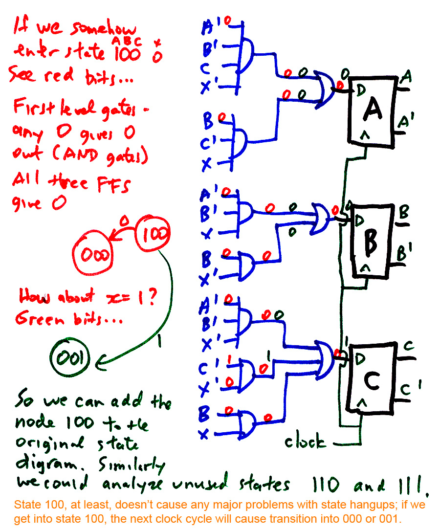
(Q)Determine the behaviour for the other two unused states in the example above. Are there any possible hangups?
(Q)Design a binary encoded FSM to the given 5-state diagram.
MANO2: p 218-228, and see below.
MANO3: p 180-190, and see below.
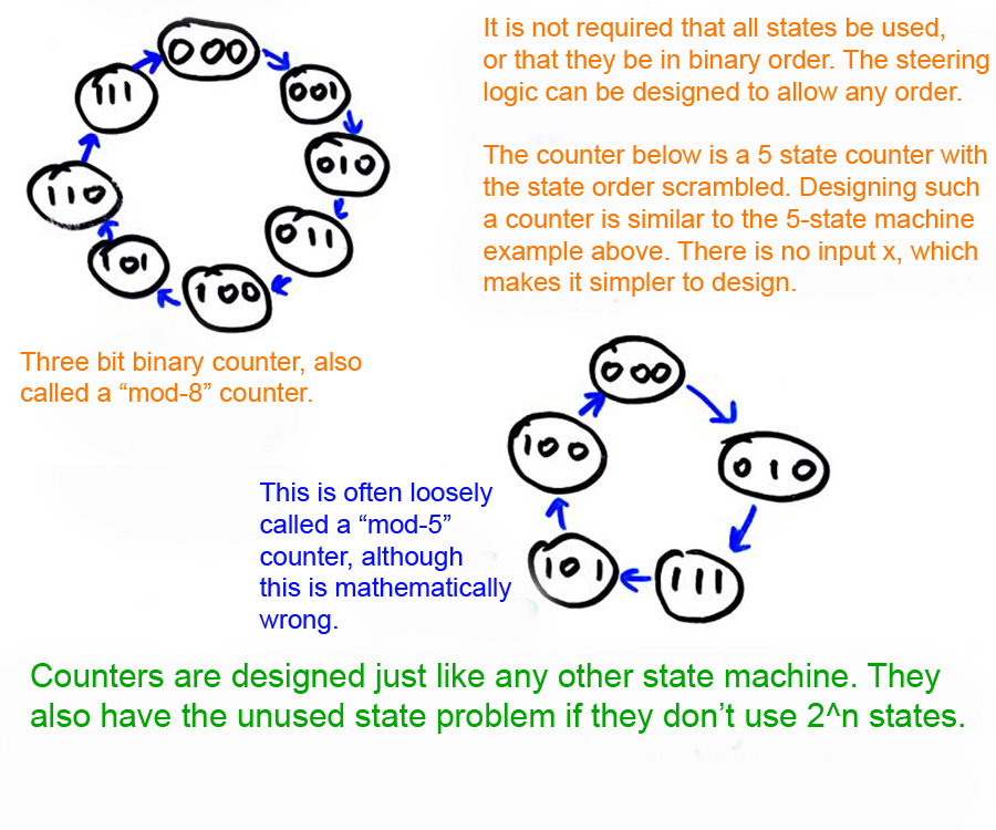
A counter is really no different from any other FSM except that is normally travels a fixed path-the state diagram is simpler. See below:
Some counters do have an input variable. For example, we could have a counter that counts up if x=0 and counts down if x=1.
(Q)Design the counters in the state diagrams above. Modify them both to allow up/down or clockwise/counterclockwise operation.
Here is an example of a rather weird counter design:
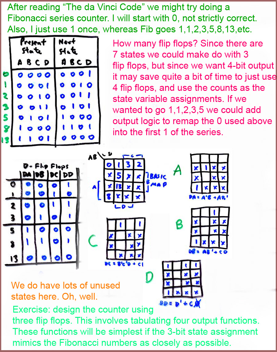
(Q)Design a counter to a given state diagram.
MANO2: p 236-251.
MANO3: p 203-211.
In addition to the binary encoded FSM, it is often desirable to make use of the one-hot FSM, in which one flip flop is used for each state. Each node in the state diagram, then, is implemented with one flip flop. This means, of course, that there are a LOT of unused states possible, since N flip flops can have 2^N states; if we use N flip flops for N states, there are thus 2^N-N unused states.
The used states are the ones with a single 1 in their binary encoding, and the rest 0. So, for a 5-state machine, the used states would be 10000, 01000, 00100, 00010, 00001.
The design process is extremely simple: the D input for each flip flop is simply the Boolean sum (i.e. OR) of all conditions pointing to that state in the state diagram.
What are the benefits? Obviously, this method uses lots more flip flops, and requires start-up help, since these machines in general are not self-starting. The main benefit is that a higher system clock speed is possible since the states need not be decoded on output. Steering logic is usually simpler, although not necessarily faster.
What do we mean by output decoding logic? Suppose we wish to design a counter that will produce a single pulse for 0, 1, 2, 3, 4, 5, 6, and 7 states. With a BESM, we would use 3 flip flops, and put a 3x8 decoder on the state variables to produce the desired 8 output lines. This decoder introduces delay. With the one-hot FSM, we just use the flip flop outputs for the same output functionality, and no other logic is needed. (Of course, if we WANTED the 3-bit binary numbers as such, then the BESM would make perfect sense, as it provides them.
(Q)BONUS How would you make an 8-stage one-hot FSM produce 3-bit binary numbers? Why would this seem a dumb thing to design?
A single node is shown below for a one-hot design; the state diagram is the one used near the top of this page:
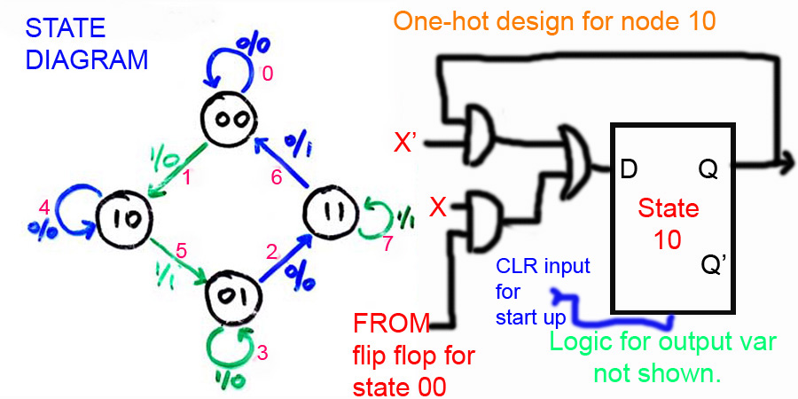
We see that this flip flop will be set to 1 if (a)it is currently 1 and X=0, OR (b)if state 00 is 1 and X is 1. In the one-hot design, only one flip flop will see a 1 input at any time.
One would probably prefer the BESM for this state diagram since the output variable Y would be a bit messy to implement with the one-hot machine. Normally, the one-hot machine is used when the individual states are needed as outputs. This is common for a control unit in a computer CPU, for example.
The starting problem typically requires that another state be added to the state diagram, an IDLE/START state, so that on power-up the machine is forced into the IDLE state, where it stays until the START signal arrives. Also, we need to use flip flops that can be forced into the desired initial state (i.e. IDLE) on start. This is done by having a CLEAR input on each flip flop except IDLE, which has a PRESET flip flop. So, on start up, the flip flops all sit at 0 except for the IDLE flip flop. The signal connecting these up can also be the IDLE control signal, which holds the FSM in the IDLE state.
We might note that if you are using flags in software for program control, as mentioned at the start of this page, you are most likely creating a one-hot machine in software. As in software, in hardware is is very possible to create a BESM/one-hot hybrid; in the bonus question below, a BESM 5-state counter could be used to produce the repeat.
(Q)Compare and contrast the basic ideas of the BESM and one-hot FSM. Compare advantages and disadvantages.
(Q)Sketch the logic for the idle state flip flop. Input (control) variables are called IDLE and START. If IDLE is true, we stay in the IDLE state. When START is true, we enter the first state of the main state sequence.
(Q)Sketch a one-hot machine that cycles through 6 states continuously (i.e. a counter). Include the start-up state as a seventh state.
(Q)BONUS sketch a circuit for a one-hot machine as in the previous question, except that each time it reaches the second state, it stays there for 5 clock cycles. Design of the 5 cycle repeat need not be one-hot. Also, include bad state detection; on a bad state it goes to an ERROR state, which is exited when an external RESTART variable is supplied.
Modern hardware development environments contain syntatical structures for implementing Boolean functions, arithmetic curcuits, MUXes, decoders, and FSMs.
MANO2: p 321-3 Not very detailed.
MANO3: p 202, p 321-3 Not very detailed.